▶ Vanadium Dioxide for RF and mmWave Applications
Vanadium dioxide (VO2) is a phase-change material (PCM) exhibiting a sharp change from an insulating state to a conductive state at a relatively low temperature of 68°C, with a minor hysteresis when cooling back to the insulating state. The highly nonlinear change can be exploited for switching, sensing, power limiting, and other applications.
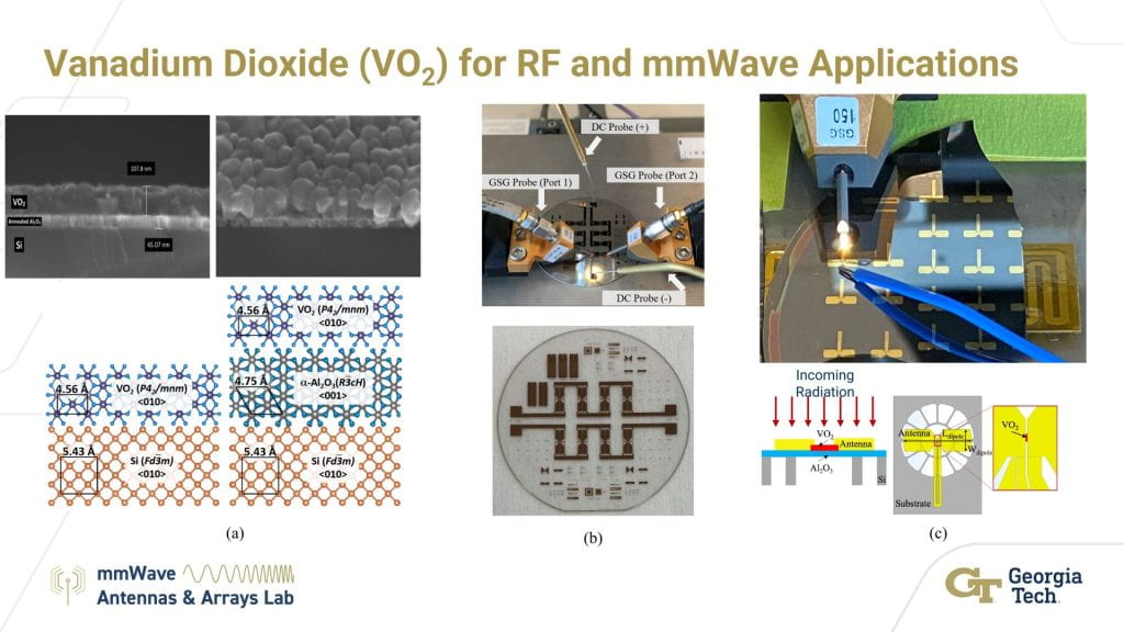
(a) Our group has extensive experience depositing and characterizing VO2. Typically, the highest-quality VO2 (exhibiting the highest resistivity ratio between its insulating and conducting states, on the order of ~105), is deposited on c-plane sapphire (Al2O3) substrates. However, silicon (Si) substrates are preferable for compatibility with standard bulk device processes. We found that inclusion of a thin annealed Al2O3 buffer layer on Si improved the lattice match with VO2, resulting in a contrast ratio on the order of 104. This work paves the way towards monolithic integration of VO2-based systems with commercial silicon processes. To characterize the quality of our thin films, we employ a four-point probe for sheet resistance measurements of the VO2.
(b) We conducted a reliability study of VO2 mmWave CPW switches on sapphire and found no statistically significant degradation of performance after 100 million switching cycles. The switches were thermally actuated using integrated joule heaters. The findings indicate that VO2’s switching mechanism is highly reliable for RF and mmWave applications.
(c) Our group experimentally demonstrated a VO2-based mmWave antenna-coupled microbolometer with a figure of merit orders of magnitude above the state-of-the-art. Typical microbolometers employ a material with a high thermal coefficient of resistance (TCR) for sensing radiation. Responsivity, which is a key figure of merit for a microbolometer, is directly related to the TCR. By biasing VO2 near 68°C, the very high TCR in the metal-insulator transition (MIT) region leads to a responsivity on the order of 104. The dipole antenna employed for the microbolometer is suspended using deep reactive ion etching to improve the coupling of incident radiation into the VO2. An array of the dipoles was characterized using a robotic measurement system.
▶ Reconfigurable Antennas and Arrays
Our group has designed reconfigurable antennas and arrays based on both mechanical and electrical reconfiguration techniques.
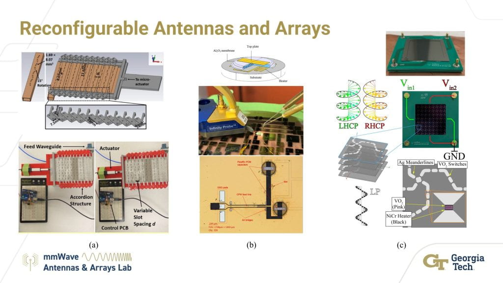
(a) A 16-GHz waveguide slot antenna array using an accordion-like structure for mechanical reconfiguration. Laser micromachining and 3D printing were used to fabricate the array and supporting structure. A microactuator expands or contracts the structure to adjust the slot spacing, allowing beam steering up to −30° from broadside.
(b) A 100-GHz bent slot antenna monolithically integrated with tunable capacitors based on paraffin, which exhibits a large reversible volumetric change between its solid and liquid phases. The capacitors were integrated with a CPW-based bent slot antenna to achieve frequency tunability at 100 GHz. A frequency extender was used on a probe station to characterize the experimental antenna.
(c) A linear-to-circular polarization (LCP) converter based on vanadium dioxide (VO2) switches operating in the Ka satcom uplink band (27.5–31 GHz). VO2 is a phase-change material (PCM) that acts as a dielectric at room temperature and exhibits a solid-state phase transition to a conducting state at 68°C [Link1, Link2]. The LCP converter is comprised of two perpendicular sets of meanderlines, each corresponding to left-hand or right-hand circular polarization (LHCP or RHCP, respectively). Each set of meanderlines is independently activated or deactivated to select the desired output polarization. A quasi-optical measurement setup [insert link to measurement page] is used to characterize the performance of the device.
▶ On-chip mmWave Antenna Arrays
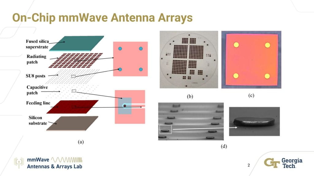
Our group has used microelectromechanical systems (MEMS) processes to improve the radiation efficiency of a 60-GHz mmWave on-chip antenna array. (a) The stack up of the proposed antenna array, including a feed structure using capacitive patches. SU-8 posts suspend the patch array above the feed structure. (b) The fabricated prototype on a fused silica wafer. (c) A single fabricated patch element with SU-8 posts. (d) SEM images of the fabricated SU-8 posts.
▶3D-Printed Antennas and Arrays
Our group has made use of additive manufacturing (3D printing) for a variety of antenna and array designs.
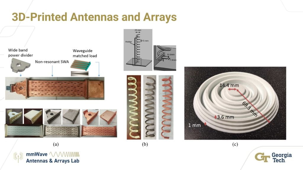
(a) A fully-3D-printed frequency scanning-slotted waveguide array (SWA) at Ku band (12–18 GHz). The wideband power-divider feed, waveguide array, and matched load termination were 3D-printed using a commercial process. The feed and array were metalized with a two-step, in-house process. Non-radiating slots were added to the narrow walls of the SWA to add more openings for the metallization chemicals to enter the cavity without affecting the field distribution.
(b) A 3D-printed helical antenna at 5 GHz. The helix and attached quarter-wave transformer were metalized with the same in-house process.
(c) A grooved 3D-printed Fresnel lens at 30 GHz. The complex permittivity of the lens material, polylactic acid (PLA), was characterized using a commercial terahertz time-domain spectroscopy (THz-TDS) system.
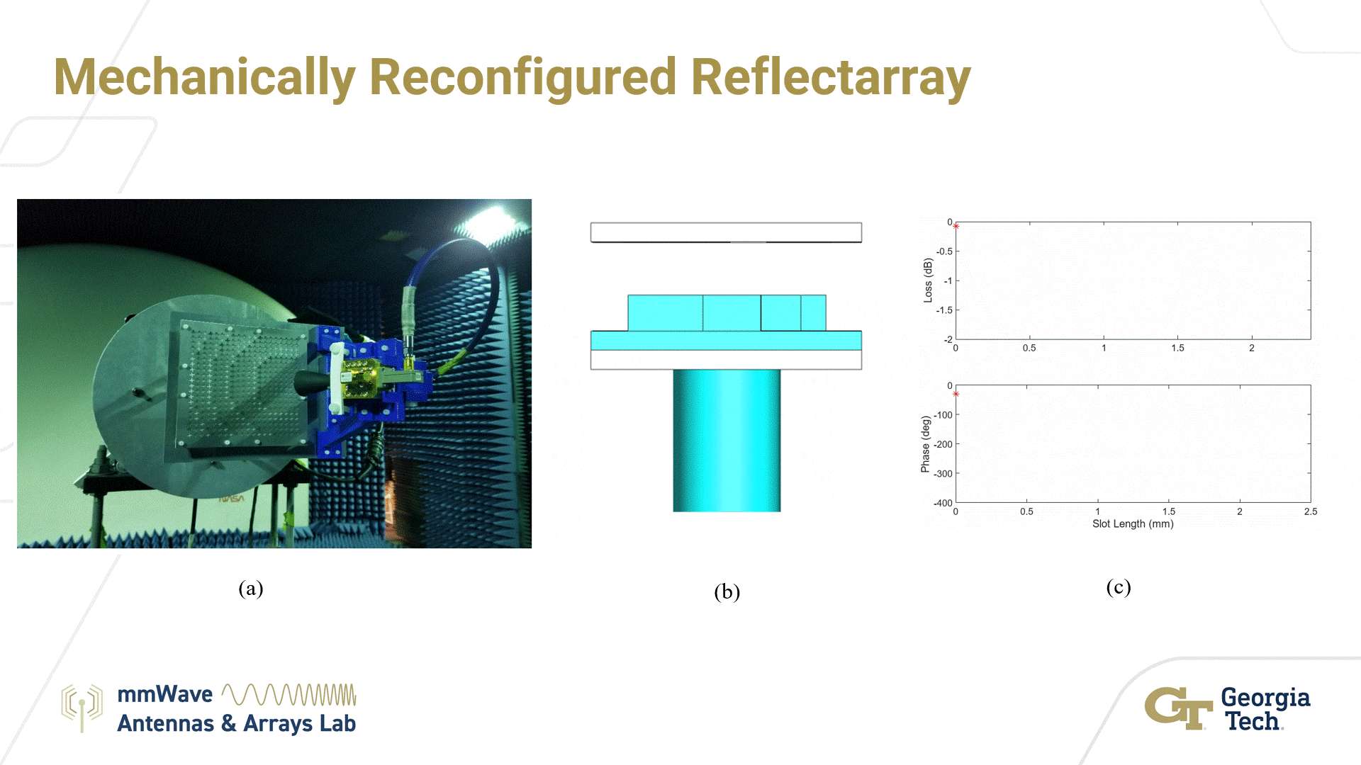
▶ Mechanically Reconfigured Reflectarray
As compared to non-linear semiconductor-based approaches (e.g. PIN diode), a mechanically reconfigured reflectarray (RRA) has the ability to handle much higher power levels albeit with a slower reconfiguration speed. With the current commercially available piezoelectric or stepper motor actuators and relays, a mechanically reconfigurable reflectarray can handle high power levels with a wide bandwidth to replace both reflector antennas and phased arrays in certain applications shown in (a). In our design, by not including a lossy active device in the path of the configured field, mechanical reconfiguration allows the RRA unit cell to stay passive. The video (b) and (c) show how the phase and reflection coefficient change in the unit cell as the height of the dielectric insert changes.
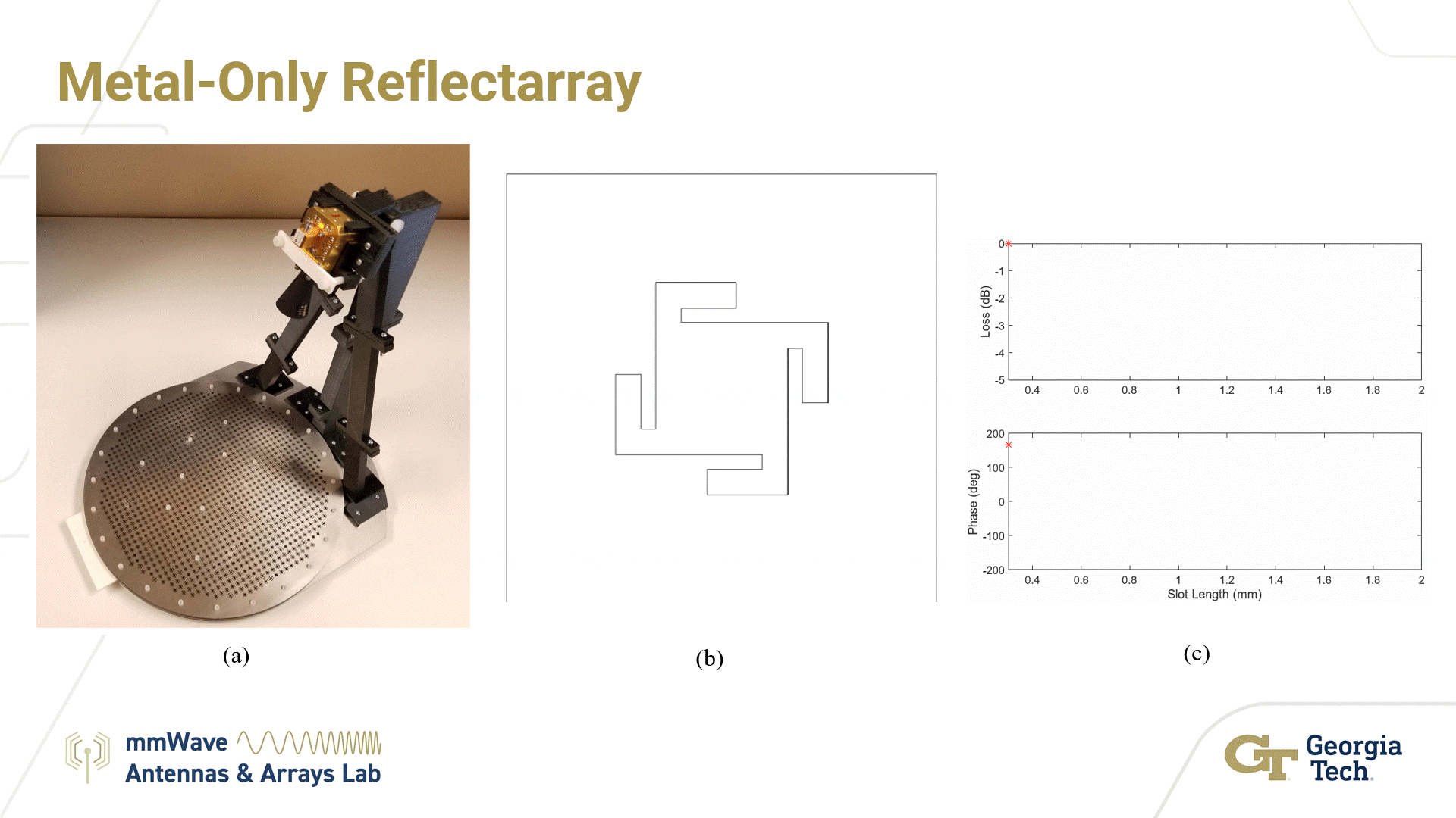
▶ Metal-Only Reflectarray
Metal-only reflectarrays completely remove the dielectric substrate from the antenna, the elements of which are machined into a high strength and corrosive-resistant metal sheet such as stainless steel or aluminum shown in (a). The metal-only unit cell supports controlling the phase of both circular and linear polarization at the same rate with unit cell. The video (b) and (c) show how the phase and amplitude of the unit cell varies with slot length.
▶ Robotically Controlled Antenna Pattern Measurement
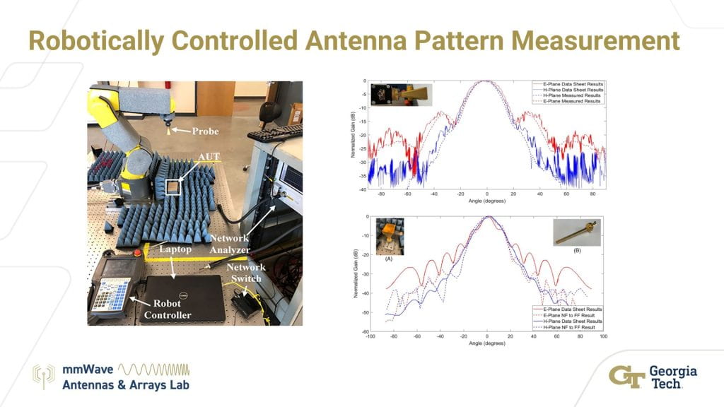
Measuring the radiation pattern in mmWave frequencies is challenging. The wavelengths at these frequencies are very small and minor misalignments can cause substation errors. To characterize mmWave antennas with high precision, we designed a robotically controlled pattern measurement system using a Fanuc LR Mate 200-iD industrial robot. The robot has a repeatability of 20 μm and has six degrees of freedom to perform precise and versatile measurements. A probe or a receiving antenna is attached to the robot’s arm, as shown in the picture. A MATLAB program controls the robot and positions the at a specified location. The robot can perform scans in planar and spherical trajectories in the vicinity of the antenna under test (AUT). Both the AUT and the probe are connected to a network analyzer to characterize the gain of AUT.
▶ Quasi-optical Free Space Measurement Setup
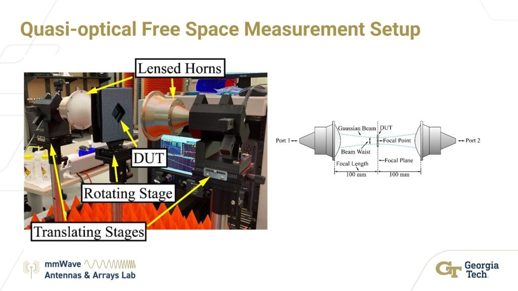
Reconfigurable Metasurfaces have been a great interest to the scientific community in the recent years. To evaluate the performance of these Metasurfaces, our group has designed a free-space method using a pair of lensed horn antennas. These lens antennas are held using a 3-D printed mount, which can be tilted to a 45-degree angle on either side. The device under test (DUT) is located at the focal plane of these antennas on a rotating stage. One antenna produces a Gaussian beam, and a planar wavefront is incident onto the DUT. The receiving antenna, placed two wavelengths away, received the gaussian beam. Both the antennas are connected to a network analyzer and the characteristics pertinent to the DUT’s performance are evaluated. The performance of a linear to circular polarization converter is tested using this setup.

▶ Magnetically Reconfigurable Devices
Our group has designed and measured electromagnetic metasurfaces that are mechanically reconfigured using small magnetic fields.
(a) This research is in collaborative effort between Georgia Institute of Technology and Stanford Mechanical Engineering led by Prof. Renee Zhao (Zhao Lab). Magnetic NdFeB unit cells are designed to reconfigure into unique geometries under the impetus of an applied magnetic field. Arrays of these magnetic unit cells become the foundation for electromagnetic metasurfaces. Moreover, these structures are flexible, enabling the design of metasurfaces that can conform to various surfaces which is unattainable using standard, rigid reconfigurable metasurfaces.
(b) The magnetic blocks are metalized to generate specific electromagnetic responses. Z-Shaped patterns are applied to generate wide band filtering from 30–35 GHz. S-Shaped patterns are applied to generate dual band filtering from 25–27 GHz and 30–34 GHz. .